It has 4 wires a white black yellow and blue. The original wiring diagram showed the proper arrangement of windings to create a larger Wye system in which there are four equal windings between any two leads.

Motor Wiring Diagrams Groschopp
Field shuntF1 F2 F3 F4 etc.
. Electric systems are subject to disturbances of many types which unavoidably produce overvoltages. The PCB has two 53ND12-Y relays on it and two diodes. Field seriesS1 S2 S3 S4 etc.
For a brushless motor with a phase angle of 120 degrees by adjusting the phase sequence of coil leads and hall leads there are six correct wires connected to the. Connect the black and yellow main motor leads in the control box to the corresponding black and yellow leads at the motor. I have bought a machine which has a 3 phase 2 speed motor and I dont have 3 phase power but I also dont want to replace the motor - I want to power it from a VFD which outputs 240v 3 phase.
Working out the wring for a 120240 volt single phase motor without at wiring diagram Suppose you have a mystery single phase induction motor 1750 rpm or 3500 rpm or very close to those RPMs. DAYTON ELECTRIC MOTOR WIRING DIAGRAM PDF Dayton Electric Mfg. It is the most reliable and recommended way to connect a generator to the home supply because when the power restores from the utility the automatic transfer switch automatically detect the power and.
I found my voltages to all be within 10 of the nominal 230VAC single-phase measurement which I deemed acceptable. Attentions help you identify a hazard avoid a hazard and recognize the consequence. IMPORTANT Identifies information that is critical for successful.
How do you wire it up. Block Diagram Logic Diagram Single Line Diagram etc. On some motors it will be six connections but some of them may be screw terminals in the wiring instead of wire.
Wye Connection Dual Voltage with Thermal Protector. However the application engineer has at his command Read more. A schematic diagram is mostly used in the electrical industry.
Ive got the wiring schematic and figured out that its a pretty standard 6-wire setup that switches 3 of the wires to be a star point and convert the 4-pole motor to a 2. There are two kinds of correct wiring for the 8 wires connecting the brushless motor with 60 degree phase angle to the controller with 60 degree phase angle one is forward rotation and the other is reverse rotation. LineL1 L2 L3 L4 etc.
Single Phase 115230V 7 Lead w Thermal Protection CW Rotation. As well as CBB61 250VAC 5060Hz It has 4 wires a white black yellow and blue. In this wiring setup there are 4 windings in series between any two Line leads.
Electrical wiring is an electrical installation of cabling and associated devices such as switches distribution boards sockets and light fittings in a structure. This is industry standardized and would be helpful for those who are about to wire up their first. Identifies information about practices or circumstances that can lead to personal injury or death property damage or economic loss.
Dec 20 2021 By Edvard. 16518 Lack of activity of the first oxygen sensor installed in row 1 17598 Invalid voltage reference for linear oxygen sensor 18675 Break or damage to the wiring supplying the first oxygen controller. The connections required for High-Voltage wiring of a Wye-wound motor.
A wiring diagram is mainly used in motor control installations and designing electrical circuits. 12 Lead Dual Voltage Y-D OR 6 Lead Single Voltage Y-D. TERMINAL MARKINGS AND INTERNAL WIRING DIAGRAMS SINGLE PHASE AND POLYPHASE MOTORS MEETING NEMA STANDARDS Dynamic braking resistorBR1 BR2 BR3 BR4 etc.
Typical 3 phase motors come with 9 labeled wires inside the junction box for either 220V or 440V hookups. Compare this to the. This document describes typical parts and a schematic for building a single to three phase rotary converter.
So that we attempted to get some good 3 wire 220v wiring diagram photo to suit your needs. Wiring Diagram Book A1 15 B1 B2 16 18 B3 A2 B1 B3 15 Supply voltage 16 18 L M H 2 Levels B2 L1 F U 1 460 V F U 2 L2 L3 GND H1 H3 H2 H4 F U 3 X1A F U 4 F U 5 X2A R Power On Optional X1 X2115 V 230 V H1 H3 H2 H4 Optional Connection Electrostatically Shielded Transformer F U 6 OFF ON M L1 L2 1 2 STOP OL M START 3 START START FIBER OPTIC TRANSCEIVER CLASS. The parts listed were taken from the 1996 Grainger catalog 387 for convenience and having a point of common reference.
Im having a hard time trying to find the wiring diagram of a YSY8218 FAN MOTOR. Single Phase Dual Voltage 11 Lead Thermally Protected CW Rotation. The control unit clarifies that the problem is related to the reference voltage.
It has a PCB lead attachment with 6 coil inputs in matching sets of three wires and what appears to be 2 matching hall sensor outputs with 7 leads each. A malfunction can lead to leaner air-fuel mixture. There are six leads or wires coming out of it.
This refers to the device installed in row 1. The connection method is same as mentioned above for single phase generator and changeover switch but we have to used three phase 4 poles manual changeover switch. It visually represents the outline for all physical components of the system and their respective positions.
Electric Motor Eight most damaging overvoltages in industrial systems root causes and prevention Electric insulation in energized systems is continuously under stress. The above fact actually makes the designing of a 3 phase BLDC motor controller pretty easy. Wiring is subject to safety standards for design and installation.
Howard St Niles IL 60714 USA retrieved 20170709 original source. Table 1 Summarizes this information to show the power system voltage and description along with the motor voltage rating for single- and 3-phase 60-Hertz motors Supply Voltage Commercial And Industrial Typical 60 Hz Power System Voltages Classification System Configuration Utilization Equipment Voltage Ratings Single Phase 3 Phase 120208 3 Phase 4 Wire Grounded. However working on your circuit breaker box and electrical system can lead to serious injury or death if you don t know what you re doing so hire an electrician if you don.
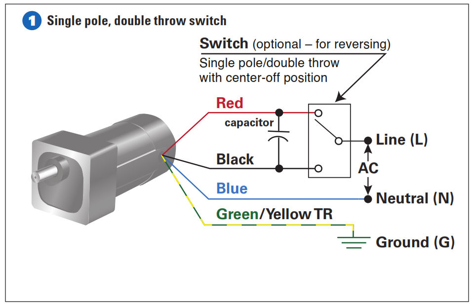
Honestly we also have been noticed that 3 wire 220v wiring diagram is being one of the most. Which may lead to personal injury or death property damage or economic loss. Finally run the green ground lead from the control box to the motor as well and land it on the motors.
Allowable wire and cable types and sizes are specified according to the circuit operating voltage and electric current capability with further restrictions on the. Im becoming slightly frustrated with the lack of information about. See also Single Phase Capacitor Start Motor Wiring Diagram - Database Before reading a schematic get common and understand all of the symbols.
Single Phase Single Voltage 3 Lead CW or CCW Rotation. For any maintenance and repairs in the. 75121 room unit air conditioner wiring diagram Sears Roebuck window air conditioner wiring diagram for a typical room or window air conditioner.
Parts list and Notes for making a 10 hp 240V single phase to 240V 3-phase converter. Wiring a single-phase 220-volt motor is straightforward. Equivalent surplus parts can be used.
Read typically the schematic like a new roadmap. Magnetizing winding for initial and maintenance magnetization and demagnetization of permanent. Also connect the red start lead from its terminal in the control box to the red lead in the motor.

Wiring Diagram For 220 Volt Single Phase Motor Http Bookingritzcarlton Info Wiring Diagram For 2 Electrical Diagram Electrical Wiring Diagram Electric Motor
How To Connect A Reversing Switch To A 3 Or 4 Wire Psc Gearmotor Bodine Gearmotor Blog

Reversing 6 Lead Single Phase Dual Voltage Motor With Forward And Reversing Starter Electrician Talk

Single Phase Motor Wiring Connection Capacitor Urdu Hindi Youtube

4 Pole Single Phase Ac Motor Wiring Electric Motors Generators Engineering Eng Tips

Single Phase 4 Pole Induction Motor Winding Diagram Electrical Circuit Diagram Electronic Circuit Projects Electrical Motor

How To Wire A Permanent Split Capacitor Psc 4 Wire Reversible Ac Motor Or Gearmotor Bodine Gearmotor Blog

How To Connect A Reversing Switch To A 3 Or 4 Wire Psc Gearmotor Bodine Electric Gearmotor Blog
0 comments
Post a Comment